TM 5-3895-373-34
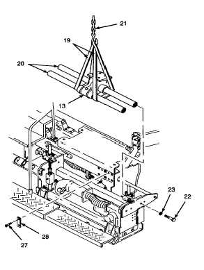
2.73 REPLACE EXTENSION SCREED GUIDE SHAFT SUPPORT, GUIDE SHAFTS, AND SLEEVE BUSHINGS -
Continued.
D.
INSTALL - Continued.
2.
INSTALL GUIDE SHAFT SUPPORT ASSEMBLY
AND
GUIDE
SHAFTS
INTO
THE
PAVING
MACHINE.
Thread locking compound can cause
eye
damage.
Wear
safety
goggles/glasses when using. Avoid
contact with eyes. If compound
contacts eyes, flush eyes with water
and get immediate medical attention.
a.
Apply thread locking compound to threads of
socket head cap screws (27).
b.
Install guide bars (28) and secure with socket
head cap screws (27).
c.
Tighten socket head cap screws (27) to 37 lb-ft
(50 N.m) using a socket wrench adapter (Item 7,
Appendix D) and hex head driver socket.
d.
Place two sling straps (19) around portion of
guide shafts (20) up against guide shaft support
assembly (13).
e.
Place loop ends of sling straps (19) into hook of
overhead hoist (21).
Guide shafts weigh approximately
200 lbs (91 kg). Ensure sling straps
and guide shaft support are centered
on guide shafts while lifting. Guide
shafts may slide in guide shaft
support.
NOTE
When lifting the guide shaft support
assembly (13) and guide shafts (20)
into the paving machine, have a
second
person
reposition
any
hydraulic hoses and electrical wiring
that may interfere with installation.
It may be necessary to spread apart
extension
screed
frame
with
universal puller kit to allow for
installation of the guide shaft support
assembly.
f.
With the help of a second person as a guide, lift
the guide shaft support assembly (13) and guide
shafts (20) into the paving machine. Align the
guide shaft support assembly with guide bars
(28).
g.
Install lockwashers (23) onto hex head cap
screws (22).
h.
Apply thread locking compound to threads of hex
head cap screws (22).
i.
Install hex head cap screws (22) through the
outer walls of extension screed and into the ends
of guide shafts (20). Do not tighten at this time.
GO TO NEXT PAGE
2-1054


