TM 5-3895-373-34
A.
REMOVE.
NOTE
This procedure applies to both the
left and right guide shaft support
assemblies. In this procedure the
right guide shaft support assembly is
shown.
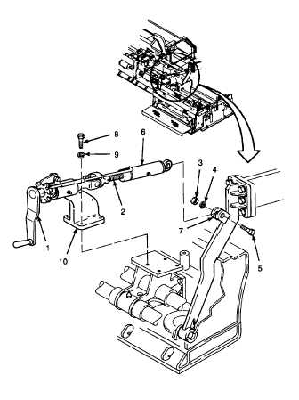
1.
REMOVE THICKNESS CONTROL ASSEMBLY.
a.
Rotate hand crank (1) to remove all tension
from threaded rod (2).
b.
Remove hex nut (3), lockwasher (4), and
hex head cap screw (5). Lift link (6) away
from screed arm bracket (7). Discard
lockwasher.
c.
Remove hex head cap screws (8) and
lockwashers (9) from thickness control
assembly
(10)
and
remove
thickness
control assembly from paving machine.
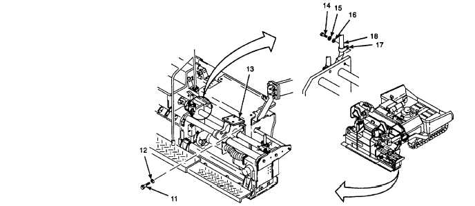
2.
REMOVE
GUIDE
SHAFT
SUPPORT
ASSEMBLY AND GUIDE SHAFTS FROM THE
PAVING MACHINE.
a.
Remove hex head cap screws (11) and
lockwashers (12) from guide shaft support
assembly (13). Discard lockwashers.
b.
Remove
hex
head
cap
screw
(14),
lockwasher (15), and flat washer (16) from
clamp (17) on front extension screed
hydraulic hose (18). Discard lockwashers.
GO TO NEXT PAGE
2-1049


