TM 5-3895-373-20
7.10.
REPLACE/REPAIR RELAY AND CIRCUIT BREAKER ASSEMBLY - Continued.
B.
ASSEMBLE - Continued.
NOTE
Inspect
all
wire
terminals
and
secondary locks to ensure locking
tabs are present and not damaged.
2.
INSTALL CIRCUIT BREAKER QUICK
DISCONNECT
TERMINALS,
BUSS
BAR
FEMALE TERMINALS, AND RELAY QUICK
DISCONNECT
TERMINALS
INTO
RELAY/CIRCUIT
BREAKER
HOLDER.
SECURE QUICK DISCONNECT TERMINALS
IN PLACE WITH SECONDARY LOCKS.
a.
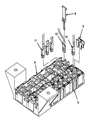
Refer to wiring diagram and connect all circuit
breaker quick disconnect terminals (10) and
buss bar female terminals (I 11). Push each
quick disconnect terminal and buss bar female
terminal into terminal cavities until an audible
click is heard.
b.
Refer to wiring diagram and connect all relay
quick disconnect terminals (12). Push each
relay quick disconnect terminal into terminal
cavities until an audible click is heard.
c.
Install secondary locks (5) into circuit breaker
cavities. Push secondary locks up from the
bottom of circuit breaker holder (6) until an
audible click is heard.
d.
Install secondary locks (8) into relay cavities.
Push secondary locks up from the bottom of
relay holder (9) until an audible click is heard.
GO TO NEXT PAGE
7-90