TM 5-3895-373-20
7.10.
REPLACE/REPAIR RELAY AND CIRCUIT BREAKER ASSEMBLY.
This task covers: a. Disassemble b. Assemble
INITIAL SETUP
Tools:
References:
General mechanic’s automotive tool kit
TM 5-3895-373-24P
(Item 54, Appendix E)
Electrical connector repair kit
Equipment Condition:
(Item 53, Appendix E)
Relay and circuit breaker assembly removed from operator
control console assembly per paragraph 7.6.
Materials/Parts:
Electrical insulating compound
(Item 11, Appendix C)
Buss bar female terminal
Circuit breaker holders
Circuit breakers
Holder legs
Quick disconnect terminal
Relay holders
Relays
Secondary locks
A.
DISASSEMBLE.
1.
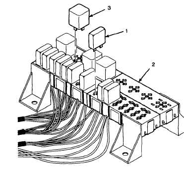
REMOVE CIRCUIT BREAKERS AND RELAYS
FROM RELAY/CIRCUIT BREAKER HOLDER.
a.
Remove circuit breakers (1) by pulling each
breaker from its terminal on relay/circuit breaker
holder (2).
b.
Remove relays (3) by pulling each relay from its
terminal on relay/circuit breaker holder (2).
GO TO NEXT PAGE
7-86