TM 5-3895-373-20
C.
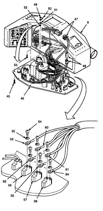
INSTALL - Continued.
d.
Install button head cap screws (53), ground
wires (52 and 51), flat washers (50), and
self-locking hex nut (49). Tighten hex nut to
9 lb-ft (12 N•m).
e.
Install ring terminals (64, 63, 62, 61, 60, and
59) with lockwashers (55) and terminal
screws (54) onto forward work light switch
(58), auger work light switch (57) and rear
work light switch (56). Refer to wiring
diagram.
WARNING
Electrical insulating varnish fumes
can be harmful if inhaled. Use only in
a
well
ventilated
area.
Avoid
prolonged exposure to fumes. If
personnel become dizzy or drowsy
during use, get immediate medical
attention.
f.
Apply electrical insulating varnish to ground
wires (52 and 51) and ring terminals (64,
63, 62, 61, 60, and 59).
g.
Apply electrical insulating compound to
male end of electrical connectors (48 and
47) and reconnect.
h.
Install tie wraps where previously removed.
i.
Install gauge panel assembly (46) into
position on operator control console.
j.
Install and tighten button head cap screws
(45).
GO TO NEXT PAGE
7-47