TM 5-3895-373-20
A.
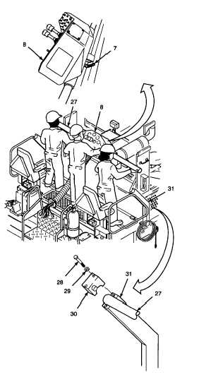
REMOVE - Continued.
3.
REMOVE
CLAMP
CAPS,
OPERATOR
CONTROL CONSOLE, AND GUIDE SHAFT
FROM CONSOLE SUPPORTS.
a.
Unlock
handle
(7)
by
turning
counterclockwise. Slide operator control
console to center of guide shaft (27). Lock
handle.
b.
Remove hex head cap screws (28),
washers (29), and clamp caps (30) from
both left and right sides.
WARNING
The operator control console and
guide shaft weigh approximately 200
lbs (90 kg). To avoid personnel
injury, use a hoist or get assistance
when lifting the control console and
guide shaft.
c.
With the help of two other persons, lift
operator control console (8) and guide
shaft (27) from console support (31) slots.
Set control console and shaft down on
operator platform.
d.
With operator control console (8) and
guide shaft (27) laying on the operator
platform, unlock handle (7) and pull the
shaft from the control console while
standing on the ground alongside the
operator platform.
e.
Set guide shaft (27) down.
f.
Remove operator control console (8) with
attached wiring harnesses from paving
machine, and set it down on a clean work
surface.
GO TO NEXT PAGE
7-27