TM 5-3895-373-20
7.6..
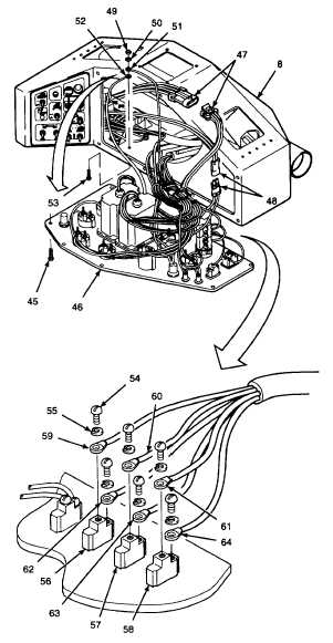
REPAIR/REPLACE OPERATOR CONTROL CONSOLE ASSEMBLY - Continued.
A.
REMOVE - Continued.
6.
REMOVE GAUGE PANEL ASSEMBLY AND
PANEL SEAL FROM OPERATOR CONTROL
CONSOLE.
a.
Remove button head cap screws (45).
CAUTION
Do not allow gauge panel assembly
to
hang
from
wires
and
wiring
harnesses. Excessive strain on wires
and wiring harnesses may result in
damaged
or
broken
wires
and
connections.
b.
Tilt gauge panel assembly (46) forward,
allowing room to work inside operator
control console (8). Do not allow gauge
panel assembly to hang from wires and
wiring harnesses.
c.
Tag and disconnect electrical connectors
(47 and 48).
d.
Cut and remove tie wraps as needed to
separate harnesses. Discard tie wraps.
e.
Remove self-locking hex nut (49), flat
washer (50), ground wires (51 and 52),
and button head cap screw (53). Discard
self-locking hex nut.
f.
Remove
terminal
screws
(54)
and
lockwashers (55) from rear work light
switch (56), auger work light switch (57),
and
forward
work
light
switch
(58).
Discard lockwashers.
g.
Tag and remove ring terminals (59, 60, 61,
62, 63, and 64).
GO TO NEXT PAGE
7-30