TM 5-3895-373-20
7.6.
REPAIR/REPLACE OPERATOR CONTROL CONSOLE ASSEMBLY - Continued.
A.
REMOVE - Continued.
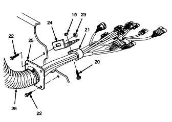
d.
Remove self-locking nut (19) and hex
head cap screw (20). Discard self-locking
nut.
e.
Remove harness clamp (21).
f.
Remove self-locking screws (22), self-
locking hex nuts (23), harness support
angle (24), and conduit mounting flange
(25), with conduit (26) attached. Discard
self-locking screw and self-locking hex
nut.
GO TO NEXT PAGE
7-26