TM 5-3895-373-20
15.19. REPAIR SCREED EXTENSION PLATE.
This task covers:
a. Disassemble
b.
Clean
c. Inspect
d. Assemble
INITIAL SETUP
Tools:
References:
General mechanic's automotive tool kit
TM 5-3895-373-10
(Item 54, Appendix E)
TM 5-3895-373-24P
Torque wrench (Item 68, Appendix E)
Wire scratch brush (Item 6, Appendix E)
Equipment Condition:
Screed extension plate removed per TM 5-3895-373-10.
Materials/Parts:
Cleaning cloth (Item 7, Appendix C)
Cleaning solvent (Item 24, Appendix C)
Self-locking nuts
NOTE
This procedure applies to both the
left and right hand screed extension
plates. Only the right side is shown
in this procedure.
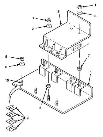
A.
DISASSEMBLE.
1.
REMOVE
SCREED
EXTENSION
BASE
FRAME.
a.
Remove self-locking nuts (1) and flat washers
(2). Discard self-locking nuts.
b.
Remove screed extension base frame (3) from
screed extension plate (4).
2.
REMOVE PLATE SPACERS.
NOTE
Plate spacers are used to align
screed extension plate with screed
plate on extension screed. There may
be no plate spacers or several plate
spacers on the screed extension
plate studs. If plate spacers are
removed, they must be returned to
the same locations from which they
were removed to maintain screed
plate alignment, or replaced with
plate spacers of like thickness.
a.
Remove self-locking nuts (5) and flat washers
(6). Discard self-locking nuts.
b.
Remove spacers (7 and 8). spacers.
c.
Remove
plate
spacers
(9)
from
screed
extension plate studs (10). Make a note of
locations of all
plate spacers.
GO TO NEXT PAGE
15-133