TM 5-3895-373-20
15.4.
REPLACE/REPAIR CROWN ADJUSTMENT ASSEMBLY - Continued.
C.
INSTALL.
1.
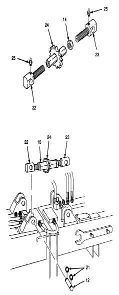
ASSEMBLE SPROCKET WHEEL AND BOLTS.
NOTE
The following procedure applies to
both the front and rear sprocket
wheel
assemblies.
The
only
difference is the hex nut is installed
on the rear sprocket wheel assembly.
a.
Apply thin coat of grease to left hand and right
hand fluid passage bolts (22 and 23).
b.
On rear sprocket assembly only, install hex nut
(14) on right hand fluid passage bolt (23).
c.
Screw right and left hand fluid passage bolts (22
and 23) into mating sides of sprocket wheel (24).
d.
Screw left hand and right hand fluid passage
bolts (22 and 23) to the same depth on both
ends of sprocket wheel (24). Count exposed
screw threads or use a steel ruler to ensure
matching bolt adjustments.
e.
Install lubrication fittings (25) into left and right
hand fluid passage bolts (22 and 23).
2.
INSTALL SPROCKET WHEEL ASSEMBLY.
Right hand fluid passage bolts of
front
and
rear
sprocket
wheel
assemblies must be on the right side
of the screed. Failure to install right
hand fluid passage bolts on the right
side will make crown adjustments
impossible
and
may
result
in
equipment damage.
a.
Position rear sprocket wheel assembly (10) on
screed. Line up pin bore of left hand fluid
passage bolt (22) with its mounting bracket.
Use care when installing retaining
rings. Retaining rings are under
spring
tension
and
can
act
as
projectiles when released and could
cause severe eye injury.
b.
Install left side assembly mounting pin (12).
Install retaining rings (21) using snap ring pliers.
c.
Hold right hand fluid passage bolt (23) so that it
does not rotate. Adjust sprocket wheel (24) to
line up pin bore of the right hand fluid passage
bolt with its mounting bracket.
d.
Install right side assembly mounting pin (12).
Install retaining rings (21) using snap ring pliers.
GO TO NEXT PAGE
15-36


