TM 5-3895-373-20
15.4.
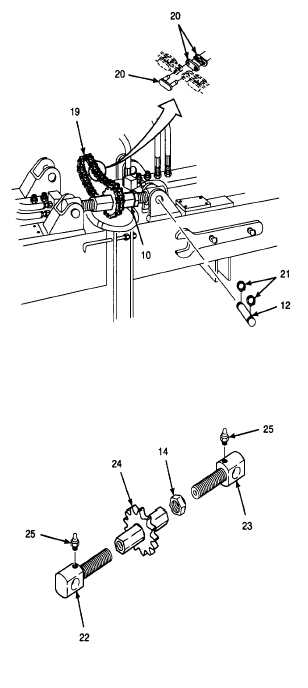
REPLACE/REPAIR CROWN ADJUSTMENT ASSEMBLY - Continued.
A.
REMOVE - Continued.
e.
Disconnect and remove chain connecting link
(20).
f.
Remove roller chain (19).
Use care when removing snap and
retaining rings. Snap and retaining
rings are under spring tension and
can act as projectiles when released
and could cause severe eye injury.
g.
Remove retaining rings (21) using snap ring
pliers. Remove assembly mounting pins (12)
and rear sprocket wheel assembly (10). Discard
retaining rings.
3.
DISASSEMBLE
SPROCKET
WHEEL
ASSEMBLY.
NOTE
The following procedure applies to
both the front and rear sprocket
wheel
assemblies.
The
only
difference is the hex nut is installed
on the rear sprocket wheel assembly.
a.
Remove left and right hand fluid passage bolts
(22 and 23) from sprocket wheel (24).
b.
Remove hex nut (14) from right hand fluid
passage bolt (23) on rear sprocket assembly.
c.
Remove lubrication fittings (25) from left and
right hand fluid passage bolts (22 and 23).
Discard lubrication fittings.
GO TO NEXT PAGE
15-34