TM 5-3895-373-10
CAUTION
During installation of outer extension
screed plate, ensure that the spacers
and plate spacers around the studs
securing the outer extension screed
plate to the frame are to allowed to
move or fall from the stud. If spacers
or plate spacers are moved and not
returned to their initial position on
the screed plate, a screed alignment
is required.
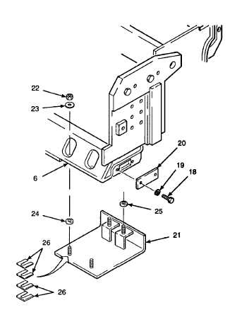
(5)
Remove self-locking nuts (22) and flat
washers (23) from outer extension screed
plate (21). Spacers (24 and 25) and plate
spacers (26) should be in place on outer
extension screed plate.
(6)
Raise outer extension screed plate (21) up
to extension screed frame (6) and secure
with flat washers (23) and self-locking nuts
(22).
(7)
Install cover plate (20) using lockwashers
(19) and hex head cap screws (18).
n.
Install endgate assembly using the following
steps.
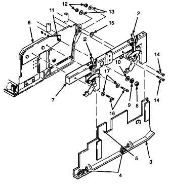
(1)
Remove hex nut (8), lockwasher (9), and
flat washer (10) from cylinder extension
rod (11).
WARNING
To avoid personal injury, do not
attempt to lift and install the endgate
support arm and endgate alone.
Endgate support arm and endgate
weighs approximately 126 lbs (57,1
kg). Use a second person to help
hold the endgate support arm and
endgate in place during installation.
Failure to do so may result in serious
injury.
(2)
With the help of a second person, lift
endgate (3) and endgate support arm (7)
onto extension screed frame (6), inserting
endgate mounting tab (5) into extension
screed
frame,
and
secure
with
flat
washers (17) and hex head cap screws
(16).
(3)
Install hex head cap screws (14), spacer
(15), flat washers (13), and self-locking
nuts (12).
(4)
Carefully level endgate (3) and connect
chains (4) to endgate hand levers (2).
(5)
Install flat washer (10), lockwasher (9),
and hex nut (8) onto cylinder extension rod
(11) and tighten hex nut.
2-93