
TM 5-3895-356-14&P
SHOULDER SPRAYING'
3. Remove pull pin on
connecting link between center half
and outer bar section on side that
is to spray 4.
Follow normal
spraying procedure
5. To spray center 6 foot
section only, remove pull pins from
connecting links between center
and outer bar sections
6. On units with "TUC" bars
Figure 22
equipped with flip valves on hinge
section and/or hook sections it is
1. Two
special
shoulder
necessary to disengage flip levers
spraying control links are provided
out to the control toggle on hook
The longer link is used to spray
dard Control Links from center
section before installing the
shoulders on the left, the shorter
fulcrum and place them in hanger
shoulder spray linkage
link for shoulders on the right To
on center control bars
use - disconnect Stan-
2. Place appropriate shoulder
link on center fulcrum
6
Remain clear of rotating drives
when unit is m operation to prevent
becoming entangled m machine
Monthly check and if necessary
7
clean 3" overflow tube to insure
tube has not become clogged
11
Keep area clear of open flame or
sparks when spraying material with
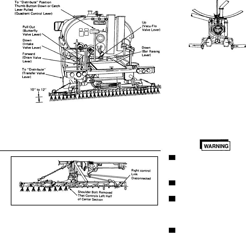
Figure 23.
volatile cutbacks to reduce fire
1. Disconnect control linkage
hazard.
for side not to spray by removing
bar. This disconnects half of center
corresponding pin in center
section that would otherwise spray
Spray bar on-off operation with air
fulcrum.
3. Follow
normal
spraying
15
will cause control lever on quadrant
procedures
2. On side to spray, remove
4. To spray center 6 foot section
to move rapidly Remain clear at all
shoulder bolt connecting control
only, remove both shoulder bolts
times to prevent injury.
linkage that connects to center
controlling valves in end sections.
section bus
17