
START-UP ADJUSTMENT
The initial crown adjustments should be made
when the screed is on the wood blocks at the starting
point and has been heated to paving temperature.
Stretch a taut string line between the ends of the hot
screed at both front and rear edges. Adjust the crown
turnbuckles (Figures 10 and 11 ) alternately a little at a
time and use a ruler to measure the distance from the
exact center of the screed bottom to the taut string
line.
Use the front and rear gauges as rough
references only! Set the front crown 1/16" higher than
the specified rear crown to start the paving.
FINAL ADJUSTMENT
The final crown adjustment is made when the
paving has been started and the actual mat crown can
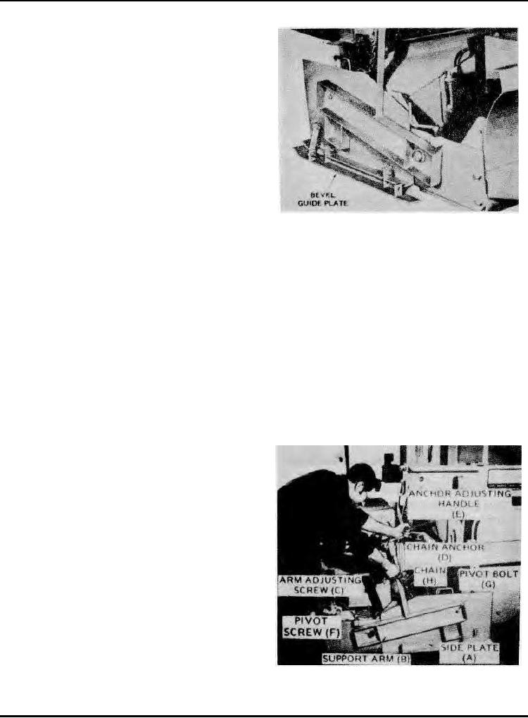
be accurately checked by taut string line. The front
Screed Side Plate & Bevel Guide Plate
crown can be varied slightly in order to obtain the very
Figure 12
best mat surface. The front crown will always be
and follow the contour of the base surface. If the
higher than the rear crown. The final adjustment
operator wishes to restrict the downward movement of
is always made after checking the actual asphalt
the plate, he adjusts the screw (C) which limits the
mat when enough has been laid to be certain the
travel of the support arm, and adjusts the chain (H) or
chain anchor handle (E).
screed has stabilized.
When bleeding material to the outside, the side
The lead crown is normally 1/16" above the
plate is raised until the end of the support arm passes
finish crown.
over center. The chain is hooked to the screed end
If any change is made in the final (trailing edge)
plate to hold the assembly in the elevated position.
crown adjustment the front (leading edge) crown
(See Figures 14 & 15)
setting must be made simultaneously to maintain the
When the screed is to be raised, the support-arm
1/16" differential.
adjusting screws (C) should be adjusted to hold the
The Dual Adjustment Assembly, which links the
side plates in line with the screed bottom. The chain
two turnbuckles by the chain and sprocket method
(H) is adjusted so that the rear end of the side plate
permits separate or simultaneous adjustment of the
cannot drop downward as the screed is raised.
two crown settings.
If only one crown needs adjusting, the coupling of
the assembly can be disengaged from the sprocket so
that each crown turnbuckle can be adjusted
separately. (See Figure 11)
Two gauges on the screen provide a crown
referencing ability for the operator. An indicator on
the rear turnbuckle shaft also provides means of
determining fine adjustments. (See Figure 11)
INSTALLING ATTACHMENTS
Side Plates (Refer to Figures 12 thru 1 5)
A side plate assembly is attached to each end of
the screed to limit the movement pf material. These
plates (A) are bolted to a support arm (B) attached to
the screed. Both parts can move in parallel planes so
that when desirable, the side plate can rest upon
Adjusting Side Plate Chain Anchor
Figure 13
Page 57