
TM 5-3895-385-23-3
0441
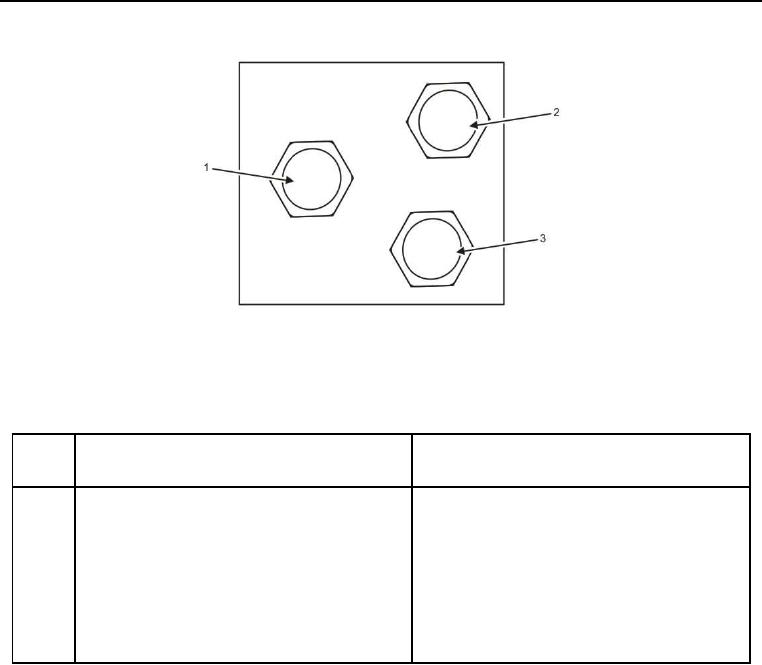
Figure 14. Vibrator/Blower Hydraulic Manifold Left Side.
Table 14. Vibrator/Blower Hydraulic Manifold Left Side.
ITEM
NO.
ITEM DESCRIPTION
DESTINATION
1
P is vibrator feed from pump. Hose 56 is
Hose 56 is connected to auxiliary pump.
connected to P.
2
BA is feed for blower motor. Hose 31 connected
Hose 31 is connected to blower motor.
to BA.
3
T is vibrator drain to hydraulic tank. Hose 50 is
Hose 50 is connected to oil cooler, which is
connected to T.
connected to hose 30 which is connected to
hydraulic tank.