
TM 5-3895-385-23-3
0441
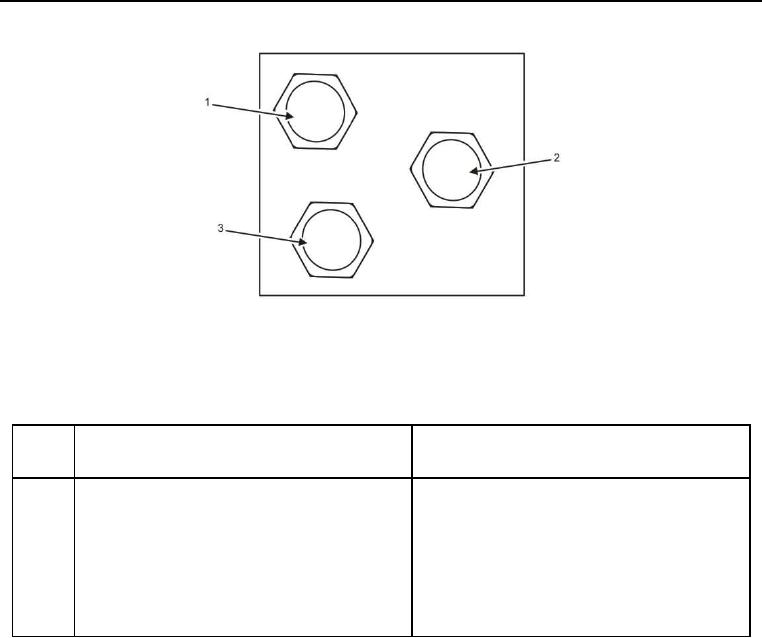
Figure 13. Vibrator/Blower Hydraulic Manifold Right Side.
Table 13. Vibrator/Blower Hydraulic Manifold Right Side.
ITEM
NO.
ITEM DESCRIPTION
DESTINATION
1
VB is drain for vibrators. Hose 19 is connected
Hose 19 is connected to bulkhead connector 18
to VB.
(Figures 22 and 23, Item 14).
2
VA is feed for vibrators. Hose 20 is connected to
Hose 20 is connected to bulkhead connector 14
VA.
(Figures 22 and 23, Item 18).
3
BB is return for blower motor. Hose 32 is
Hose 32 is connected to blower motor.
connected to BB.