
TM 5-3895-385-23-3
0441
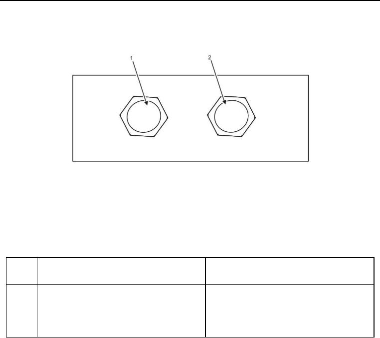
Figure 19. Flow Divider Auger Lift Manifold Bottom Side.
Table 19. Flow Divider Auger Lift Manifold Bottom Side.
ITEM
NO.
ITEM DESCRIPTION
DESTINATION
1
A is right auger lift cylinder extend. Hose 76 is
Hose 76 is connected to the extend side of the
connected to A.
right auger lift cylinder.
2
B is right auger lift cylinder retract. Hose 77 is
Hose 77 is connected to the retract side of the
connected to B.
right auger lift cylinder.