
TM 5-3895-385-23-3
0441
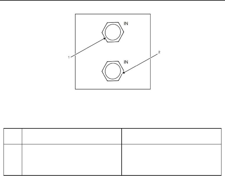
Figure 11. Hopper Wing Hydraulic Manifold Front Side.
Table 11. Hopper Wing Hydraulic Manifold Front Side.
ITEM
NO.
ITEM DESCRIPTION
DESTINATION
1
In (B) is side wing cylinder retract. Hose 49B is
Hose 49B is connected to SWB on Main
connected to In (B).
Hydraulic Manifold (Figure 3, Item 12).
2
In (A) is side wing cylinder extend. Hose 49A is
Hose 49A is connected to SWA on Main
connected to In (A).
Hydraulic Manifold (Figure 3, Item 15).