
TM 5-3895-385-23-3
0441
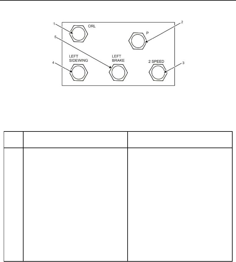
Figure 10. Hopper Wing Hydraulic Manifold Left Side.
Table 10. Hopper Wing Hydraulic Manifold Left Side.
ITEM
NO.
ITEM DESCRIPTION
DESTINATION
1
Left side wing cylinder retract. Hose 9B is
Hose 9B is connected to tee, which is
connected.
connected to hose 4 and 5 which is connected
to the retract side of both left side wing
cylinders.
2
P is pump feed for hopper wing hydraulic
Hose 28 is connected to M6 on the left side of
manifold. Hose 28 is connected to P.
the auger conveyor pump.
3
2 Speed is left torque hub 2 speed
Hose 11 is connected to M3 on left drive motor.
engage/disengage. Hose 11 is connected to 2
Speed.
4
Left side wing cylinder extend. Hose 9A is
Hose 9A is connected to tee, which is
connected.
connected to hose 3 and 6 which is connected
to the extend side of both left side wing
cylinders.
5
Left Brake is left torque hub brake
Hose 13 is connected to BRK PRT on left drive
engage/disengage. Hose 13 is connected to
motor.
Left Brake.