
TM 5-3895-385-23-3
0441
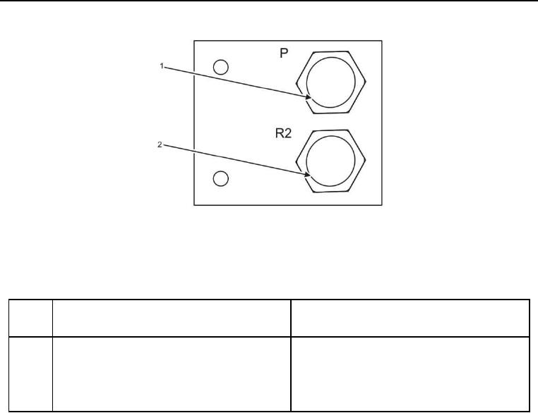
Figure 5. Main Hydraulic Manifold Front Side.
Table 5. Main Hydraulic Manifold Front Side.
ITEM
NO.
ITEM DESCRIPTION
DESTINATION
1
P is pump feed for main hydraulic manifold.
Hose 18 is connected to Port P on the right side
Hose 18 is connected to P.
of the rear pump on the auger conveyor pump.
2
R2 (T) is main hydraulic manifold drain to the
Hose 26 is connected to the hydraulic tank.
hydraulic tank. Hose 26 is connected to R2 (T).