
TM 5-3895-385-23-2
0423
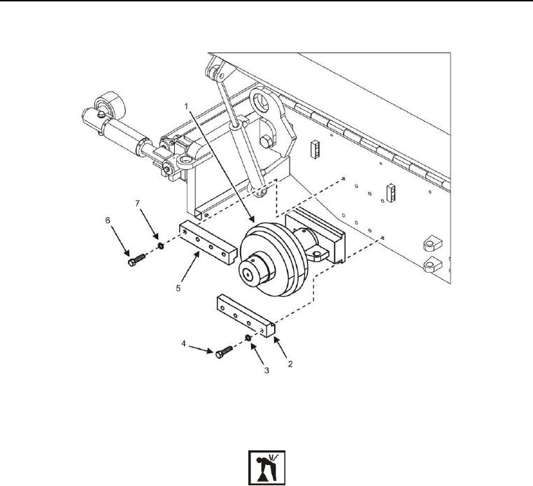
Front Idler Assembly Installation
Figure 2. Front Idler Assembly.
WARNING
The front idler assembly weighs 208 lb (94 kg). Use a suitable lifting device. Failure to comply
may cause injury or death to personnel.
CAUTION
Properly support the item being lifted. Failure to comply may cause damage to equipment.
1. Install front idler assembly (Figure 2, Item 1), four bolts (Figure 2, Item 4), new lock washers (Figure 2, Item
3), and bottom idler slide tap bar (Figure 2, Item 2) onto BMPM with assistance.
2. Install four bolts (Figure 2, Item 6), new lock washers (Figure 2, Item 7), and top idler slide tap bar (Figure 2,
Item 5) onto BMPM.
END OF TASK