
TM 5-3895-385-23-2
0277
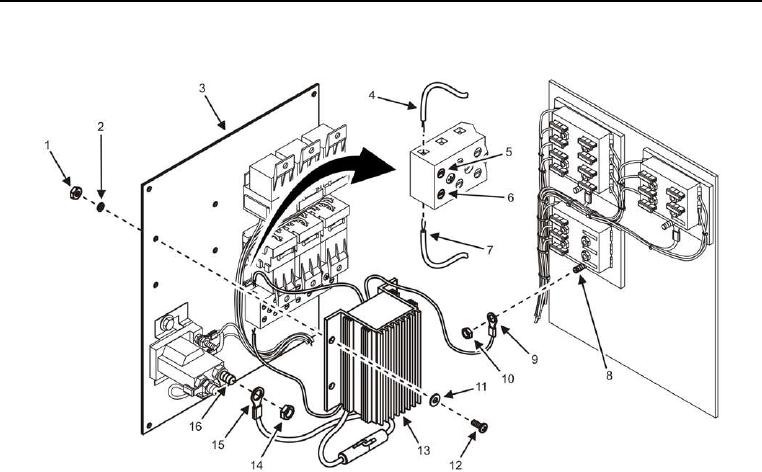
Fuse Box Assembly -- Continued.
Figure 14. Transformer.
6. Install four nuts (Figure 14, Item 1), new lock washers (Figure 14, Item 2), flat washers (Figure 14, Item 11),
screws (Figure 14, Item 12), and transformer (Figure 14, Item 13) into fuse box panel (Figure 14, Item 3).
7. Install two ground wires (Figure 14, Items 4 and 7) into ground block and tighten two screws (Figure 14, Items
5 and 6).
8. Install nut (Figure 14, Item 10) and red transformer wire (Figure 14, Item 9) into fuse block (Figure 14, Item 8).
9. Install nut (Figure 14, Item 14) and orange transformer wire (Figure 14, Item 15) into power relay (Figure 14,
Item 16).
10. Install inline fuse (perform step 1 of Inline Fuse Installation task).