
TM 5-3895-385-23-2
0277
Fuse Box Assembly
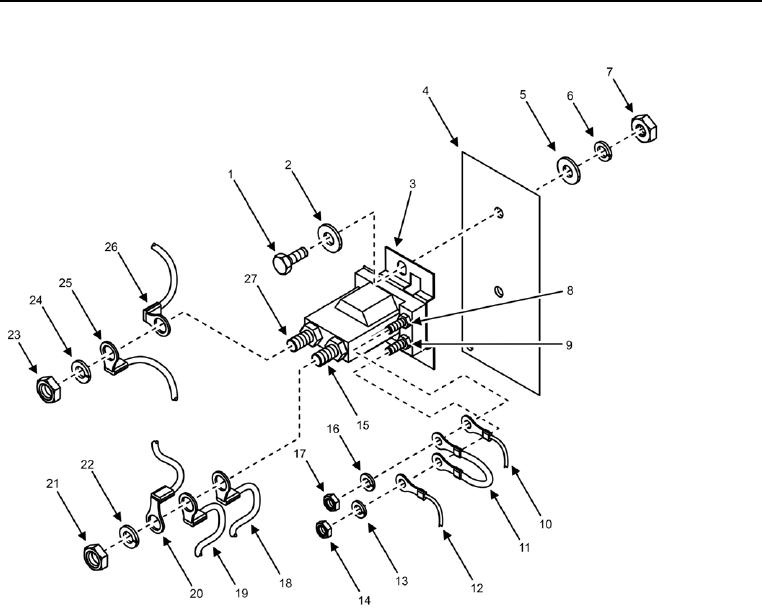
Figure 13. Power Relay.
1. Install two nuts (Figure 13, Item 7), two new lock washers (Figure 13, Item 6), four flat washers (Figure 13,
Items 2 and 5), two bolts (Figure 13, Item 1), and power relay (Figure 13, Item 3) onto fuse box panel (Figure
13, Item 4).
2. Install nut (Figure 13, Item 14), new lock washer (Figure 13, Item 13), and three wires (Figure 13, Items 10,
11, and 12) onto post (Figure 13, Item 9).
3. Install nut (Figure 13, Item 17), new lock washer (Figure 13, Item 16), and two wires (Figure 13, Items 10 and
11) onto post (Figure 13, Item 8).
4. Install nut (Figure 13, Item 21), new lock washer (Figure 13, Item 22), and three wires (Figure 13, Items 18,
19, and 20) onto post (Figure 13, Item 15).
5. Install nut (Figure 13, Item 23), new lock washer (Figure 13, Item 24), and two wires (Figure 13, Items 25 and
26) onto post (Figure 13, Item 27).