
TM 5-3895-385-23-2
0240
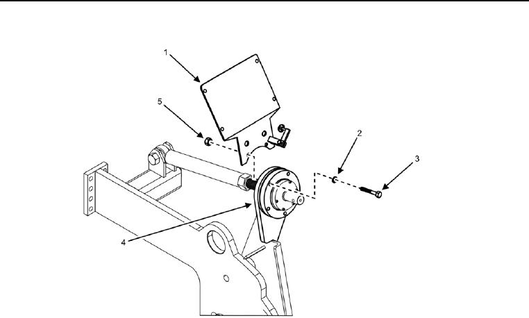
Screed Control Box Lower Mount Removal
Figure 9. Screed Control Box Lower Mount.
1. Remove screed control box (perform steps 1 9 of Screed Control Box Removal task).
2. Remove two bolts (Figure 9, Item 3), lock washers (Figure 9, Item 2), locking nuts (Figure 9, Item 5), and
screed control box lower mount (Figure 9, Item 1) from flight screw assembly (Figure 9, Item 4). Discard lock
washers and locking nuts.
END OF TASK
Screed Control Box Lower Mount Installation
1. Install two bolts (Figure 9, Item 3), new lock washers (Figure 9, Item 2), new locking nuts (Figure 9, Item 5),
and screed control box lower mount (Figure 9, Item 1) to flight screw assembly (Figure 9, Item 4).
2. Install screed control box (perform steps 1 9 of Screed Control Box Installation task).
END OF TASK