
TM 5-3895-385-23-2
0240
Screed Control Box Installation
1. Install screed control box (Figure 5, Item 2), three bolts (Figure 5, Item 4), six flat washers (Figure 5, Items 3
and 5), and three new locking nuts (Figure 5, Item 6) to screed control box lower mount (Figure 5, Item 1).
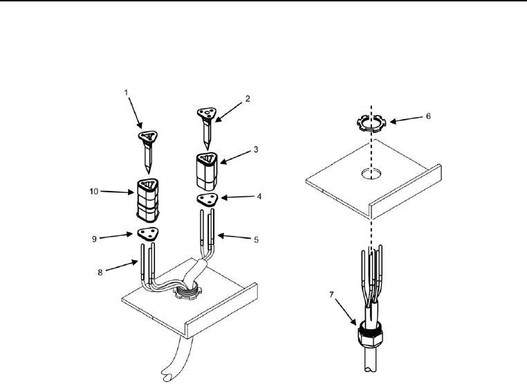
Figure 6. Wiring Harness -- Installation.
2. Install cable harness (Figure 6, Item 7) and wires (Figure 6, Items 5 and 8) into screed control box, being
careful not to damage wires.
3. Install star nut (Figure 6, Item 6) over cable harness (Figure 6, Item 7).
4. Insert wires (Figure 6, Items 5 and 8) into rear grommets (Figure 6, Items 4 and 9).
5. Insert wires (Figure 6, Items 5 and 8) into connectors (Figure 6, Items 3 and 10) until the wires seat properly
into connectors.
6. Install wedge caps (Figure 6, Items 1 and 2) into connectors (Figure 6, Items 3 and 10).