TM 5-3895-373-34
2.66.
REPLACE EXTENSION SCREED FRAME - Continued
D.
INSTALL - Continued.
h.
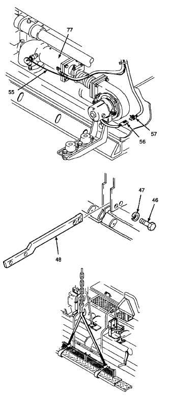
Apply electrical insulating compound to screed
harness electrical connector (57).
i.
Plug blower motor electrical connector (56) into
screed harness electrical connector (57).
j.
Install tie wraps to secure lead wire (55) away
from burner chamber (77).
k.
Start engine per TM 5-3895-373-10. Raise
screed. Extend and retract extension screed
to ensure freedom of movement of hydraulic
and fuel hoses. Remove and relocate tie
wraps as required.
l.
Shut down engine per TM 5-3895-373-10.
11.
INSTALL SCREED STEPS.
a.
If only left hand main screed was removed,
proceed to step b. If right hand main screed
was removed, temporarily secure center step
support (48) to main screed with hex head cap
screws (46) and lockwashers (47). Do not fully
tighten cap screws at this time.
Handrail and attaching steps weigh
approximately
120
lbs
(55
kg).
Personnel shall stay clear of objects
being lifted during hoist operations.
Do not work on objects suspended
by a hoist. A swinging or shifting
load may cause injury or death to
personnel.
b.
With overhead lifting device, sling straps, and
the help of a second person, raise handrail
with attached steps. Position and lower
handrail and steps into approximate mounting
location on screed.
GO TO NEXT PAGE
2-922