TM 5-3895-373-34
2.66.
REPLACE EXTENSION SCREED FRAME - Continued
D.
INSTALL - Continued.
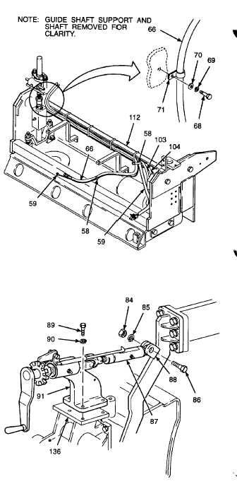
1.
Route screed harness (59) and screed burner fuel
hose (66) through conduit channel of extension
screed frame (112).
m.
Install lockwasher (69) and flat washer (70) to
hex head cap screw (68).
Thread locking compound can cause
eye
damage.
Wear
safety
goggles/glasses when using. Avoid
contact with eyes. If compound
contacts eyes, flush eyes with water
and get immediate medical attention.
n.
Apply thread locking compound (Item 14,
Appendix B) to hex head cap screw (68) and
secure clamp (71) and burner fuel hose (66) to
extension screed frame inner plate.
o.
Install tie wraps (58) on screed harness (59),
screed burner fuel hose (66), and hydraulic
hoses (103 and 104). Refer to opposite
extension screed for proper tie wrap locations.
8.
INSTALL THICKNESS CONTROL COMPONENTS.
a.
Set screed thickness control mounting bracket
(91) on guide shaft support (136). Align
mounting bracket mounting holes.
b.
Install lockwashers (90) onto hex head cap
screws (89).
c.
Apply thread locking compound (Item 13,
Appendix B) to threads of hex head cap
screws (89).
d.
Install
hex
head
cap
screws
(89)
and
lockwashers (90). Tighten hex head cap
screws to 90 lb-ft (122 N•m).
e.
Insert link (87) in screed arm bracket (88) and
install hex head cap screw (86) and lockwasher
(85). Apply thread locking compound (Item 13,
Appendix B) to threads of cap screw.
f.
Install hex nut (84). Tighten hex nut to 180 lb-ft
(244 N•m)
GO TO NEXT PAGE
2-918