TM 5-3895-373-34
D.
INSTALL - Continued.
c.
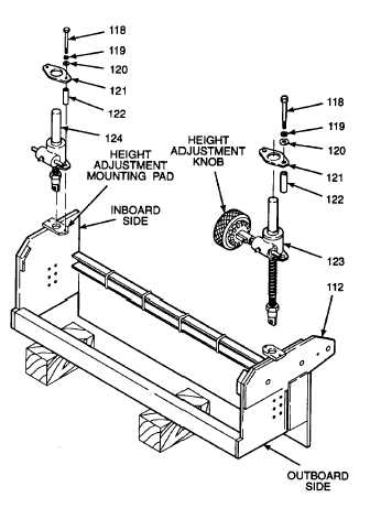
Insert lift jack assemblies (124 and 123) into
mating bores of extension screed frame (112).
The lift jack equipped with a height adjustment
knob goes on outboard side of screed frame.
d.
Install lockwashers (119) and flat washers
(120) on hex head cap screws (118). Insert
cap screws through flange plate (121) and
spacers (122).
Thread locking compound can cause
eye
damage.
Wear
safety
goggles/glasses when using. Avoid
contact with eyes. If compound
contacts eyes, flush eyes with water
and get immediate medical attention.
e.
Apply thread locking compound (Item 14,
Appendix B) to threads of hex head cap
screws (118).
f.
Place flange plates (121) with installed spacers
(122) and hex head cap screws (118) over
lift jack assemblies (124 and 123).
g.
Line up hex head cap screws (118) with holes
in lift jack assemblies (124 and 123) and
height adjustment mounting pads. Install cap
screws. Tighten cap screws to 37 Ib-ft (50
N•m).
GO TO NEXT PAGE
2-911