TM 5-3895-373-34
D.
INSTALL.
NOTE
The following procedures show right
hand
extension
screed
components
only. The left hand extension screed is
a mirror image of the right hand
extension
screed.
All
installation
procedures
are
the
same,
unless
otherwise indicated.
1.
INSTALL EXTENSION SCREED VIBRATOR
COMPONENTS PER PARAGRAPH 2.75.
2.
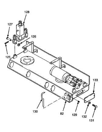
INSTALL
COVER
PLATE
AND
HEIGHT
ADJUSTMENT
INDICATOR
ON
EXTENSION
SCREED BASE.
Thread locking compound can cause
eye damage.
Wear
safety
goggles/glasses
when
using. Avoid contact with eyes. If
compound contacts eyes, flush eyes
with water and get immediate medical
attention.
a.
Install lockwashers (132) on hex head cap
screws (131). Apply thread locking compound
(Item 14, Appendix B) to cap screw threads.
b.
Install cover plate (133) and hex head cap
screws (131). Tighten cap screws to 9 lb-ft
(12 N•m).
NOTE
Height adjustment indicator will be
repositioned
during
screed
plate
alignment procedure. Position of
indicator in its mounting is not important
at this time.
c.
Install height adjustment indicator (130) and
secure with socket set screws (129).
3.
INSTALL EXTENSION SCREED GUIDE SUPPORT
ASSEMBLY AND SHAFTS PER PARAGRAPH
2.73.
4.
INSTALL HEIGHT ADJUSTMENT COMPONENTS.
a.
Line up devises on vertical adjustment block
assemblies (128) with mating bosses on
extension screed base (82).
b.
Install clevis pins (127), flat washers (126), and
cotter pins (125). Spread cotter pins to secure
clevis pins.
GO TO NEXT PAGE
2-910