TM 5-3895-373-34
2.66.
REPLACE EXTENSION SCREED FRAME - Continued
C. INSPECT.
1.
INSPECT EXTENSION SCREED FRAME.
a.
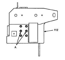
Install four 3/8-16 UNC x 4 in. hex head cap
screws in holes A, located at each end of
extension screed frame (112). Secure each
cap screw with a 3/8-16 UNC hex nut on each
side of extension screed frame plate.
b.
Suspend extension screed frame (112) on
inspection angle plates. The screed frame
must be supported only by the hex head cap
screws installed in holes A.
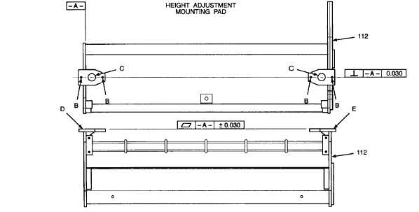
c.
Check for perpendicularity between surface A
and the lines that pass through the centers of
threaded holes B and bores C of each height
adjustment mounting pad.
If
either
mounting
pad
centerline,
when
projected 46 in. (1168 mm) from surface A, is
not within 1/16 in. (1,6 mm) of the line
perpendicular to surface A, replace warped
screed frame.
d.
Place a straightedge (at least 4 feet long)
across surfaces D and E. If any point on
surface D or E is not within 1/16 in. (1,6 mm)
of the straightedge, replace warped extension
screed frame.
e.
Visually inspect extension screed frame weld
joints for cracks or breaks. If cracks or breaks
are
found,
replace
screed
frame.
GO TO NEXT PAGE
2-908