TM 5-3895-373-34
NOTE
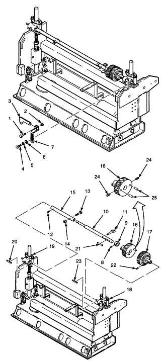
This procedure applies to both the left
and right extension screed. For this
procedure, the right extension screed is
shown. Throughout this procedure, the
main screed is not shown for clarity.
A.
REMOVE.
1.
ROTATE HEIGHT ADJUSTMENT KNOBS TO
LOWER EXTENSION SCREED PLATE UNTIL IT IS
RESTING FLAT ON A LEVEL SURFACE PER TM 5-
3895-373-10.
2.
REMOVE MOUNTING BRACKET AND CATCH
PLATE.
a.
Remove hex head cap screw (1), self-locking
hex nut (2), and catch plate (3). Discard self-
locking hex nut.
b.
Remove hex head cap screws (4), lockwashers
(5), and flat washers (6). Discard lockwashers.
c.
Remove mounting bracket (7).
3.
REMOVE LIFT JACK ASSEMBLY CONNECTING
SHAFT AND HEIGHT ADJUSTMENT KNOBS.
a.
Remove set screw (8).
b.
Slide stop ring (9) toward center of shaft (10).
c.
Pull quick release pin (11) free of shaft (10).
d.
Remove set screws (12), hex head cap screw
(13), and self-locking hex nut (14) from coupling
(15). Discard self-locking hex nut.
e.
Slide shaft (10) into coupling (15) and separate
shaft and inner height adjustment knob (16) from
outer height adjustment knob (17).
f.
Slide coupling (15) with shaft (10) and inner
height adjustment knob (16) from outer lift jack
assembly (18) and inner lift jack assembly (19).
Remove from extension screed.
g.
Remove key (20) from inner lift jack assembly
(19) shaft.
h.
Remove coupling (15), inner height adjustment
knob (16), key (21), and stop ring (9) from shaft
(10).
i.
Remove set screw (22), outer height adjustment
knob (17), and key (23) from outer lift jack
assembly (18).
j.
Remove
set
screws
(24)
from
inner
height
adjustment knob (16) and remove pins (25) using a pair
of pliers
GO TO NEXT PAGE
2-801