TM 5-3895-373-34
E.
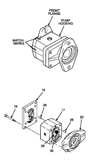
ASSEMBLE - Continued.
m.
Carefully pick up front flange and rotate seal
face to vertical position. Align matchmarks on
flange perimeter with matchmarks on pump
housing.
n.
Carefully support installed bearing unit (29) at
rear of pump housing (17) with one hand, and
slide front flange (20) squarely over long end
shaft of drive gear (30) with the other hand.
o.
Line up installed guide pins (26) with guide pin
holes in front flange (20). Fully seat face of front
flange against face of pump housing (17).
p.
Carefully pick up rear cover (18) and rotate seal
face to vertical position. Align matchmarks and
line up guide pin holes in rear cover with
installed guide pins (26). Fully seat face of rear
cover against face of pump housing (17).
q.
With both ends of auxiliary vibration pump
clamped firmly in one hand, install and finger
tighten socket head cap screws (19).
Do not clamp vise jaws against pump
housing. Clamping against pump
housing walls can deform internal
cavities
and
cause
permanent
damage to the auxiliary vibration
pump.
r.
Clamp rear cover (18) in vise jaw caps of bench
vise to secure auxiliary vibration pump. Evenly
tighten
socket
head
cap
screws
(19)
in
increments, using a diagonal tightening pattern.
Tighten cap screws to 39 lb-ft (53 N•m).
Hydraulic
oil
can
be
moderately
flammable and can be an irritant to
the
skin,
eyes,
and
respiratory
system. Avoid prolonged exposure.
Eye protection and rubber gloves
must be worn when working with
hydraulic oil.
s. Pour a small amount of clean hydraulic oil into
inlet port of auxiliary vibration pump. Place
pump on machinery wiping towel.
GO TO NEXT PAGE
2-599