TM 5-3895-373-34
E.
ASSEMBLE - Continued.
5.
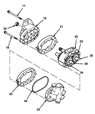
ASSEMBLE BACKPLATE ASSEMBLY, ADAPTER
PLATE ASSEMBLY, AND FRONT PLATE ASSEMBLY.
a.
Apply petrolatum to preformed packing (43).
Install packing in mating groove of backplate
assembly (23).
Hydraulic
oil
can
be
moderately
flammable and can be an irritant to
the
skin,
eyes,
and
respiratory
system. Avoid prolonged exposure.
Eye protection and rubber gloves
must be worn when working with
hydraulic oil.
b.
Dip adapter plate assembly (22) with installed
drive and idler gears (33 and 34) and drive and
idler gear assemblies (35 and 36) in clean
hydraulic oil.
NOTE
Pump
components
must
be
assembled in same positions as they
were prior to disassembly.
c.
Apply a thin coat of clean hydraulic oil to insides
of pump bodies (20 and 21).
d.
Align matchmarks on adapter plate assembly
(22) and installed rear pump body (20) with
backplate assembly (23). Install backplate
assembly on assembled adapter plate assembly
and pump body.
e.
Align matchmarks and join front plate assembly
(19) and installed front pump body (21) with
adapter plate assembly (22).
NOTE
Longer hex head cap screws (17) are
installed inside pilot diameter of
pump mounting flange f. Install hex
head cap screws (18 and 17). Tighten
to 26 lb-ft (35 N•m).
g.
Lubricate shaft seal (32) with clean hydraulic oil.
Use caution when installing shaft
seal. Sharp edges on drive shaft may
cut seal. Install shaft seal slowly. Do
not use excessive pressure to install
shaft seal.
h.
Using 3/4 in. deep well socket install shaft seal
(32) over shaft of drive gear assembly (35) and
into bore of front plate assembly (19). Tap on
3/4 in. deep well socket until shaft seal is fully
seated. Ensure spring loaded lip faces front
plate assembly.
i.
Rotate shaft of drive gear assembly (35) by
hand. Shaft should have slight resistance.
GO TO NEXT PAGE
2-579