TM 5-3895-373-34
E.
ASSEMBLE Continued.
5.
INSTALL O-RING, FRAME AND BRUSH
ASSEMBLY, AND COMMUTATOR END FRAME
ONTO
DRIVE
HOUSING
AND
ARMATURE
ASSEMBLY. INSTALL MOTOR LEAD ONTO
SOLENOID.
a.
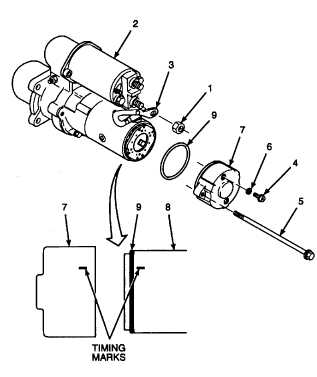
Install o-ring (9) on frame and brush assembly
(8), positioning o-ring against shoulder of frame
and brush assembly that contacts commutator
end frame (7).
b.
Slowly roll out o-ring (9) from its position against
the frame and brush assembly shoulder until it is
on the outer diameter of the frame and brush
assembly.
c.
Align match marks on commutator end frame (7)
and frame and brush assembly (8).
d.
Position commutator end frame (7) onto frame
and brush assembly (8), leaving a gap slightly
larger than o-ring diameter.
e.
Use a drift punch to align tapped holes in brush
holder assembly and commutator end frame (7).
f.
Install preformed packing (6) and brush plate
screws (4). Tighten screws to 25 lb-in (2, 8
N.m).
g.
Without closing gap between commutator end
frame (7) and frame and brush assembly (8),
install screws (5) and tighten by hand.
h.
Roll
o-ring
(9)
down
into
gap
between
commutator end frame (7) and frame and brush
assembly (8).
NOTE
Timing marks are located in two
places, but will only align one way.
i.
Align timing mark on edge of commutator end
frame (7) with timing mark on frame and brush
assembly (8)..
j.
Tighten screws (5) on commutator end frame (7)
to 75 Ib-in (8, 5 N•m)
.
k. Remove hex nut (1) from terminal on solenoid
(2).
l. Install motor lead (3) onto the terminals marked
during disassembly
m.
Install hex nut (1). Tighten to 100 lb-in (11 N•m).
GO TO NEXT PAGE
2-351


