TM 5-3895-373-34
2.25
REPAIR STARTER ASSEMBLY - Continued
E.
ASSEMBLE Continued.
i.
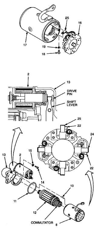
Position brush holder assembly (16) close to
frame/field assembly (17).
j.
Install lockwashers (19) onto screws (18).
k.
Attach insulated brush (25) leads to frame/field
assembly (17) with screws (18).
l.
Tighten screws (18) to 13 lb-in (1, 5 N•m).
4.
INSTALL SOLENOID INTO DRIVE HOUSING.
a. Install solenoid (2) into shift lever by tilting rear of
solenoid downward and pushing toward drive
housing (13), then leveling solenoid. Make sure
that pin on the end of the solenoid engages the
shift lever.
b. Position solenoid (2) onto drive housing (13) by
matching up holes for screws (14).
c.
Install lockwashers (15) onto screws (14).
d. Install screws (14). Tighten to 25 lb-in (2, 8 N
m).
e. Install preformed packing (11) onto frame and
brush assembly (8).
f. Install armature (12) into drive housing (13) by
aligning gear teeth on armature, seat bearing
fully in far end of drive housing.
g. Place dowel pin (10) into drive housing (13).
h. Position frame and brush assembly (8) over
armature (12), aligning hole for dowel pin (10).
i. Move brush springs (22) away from grounded
brushes (24) and insulated brushes (25).
j. Slide brushes (24 and 25) inward to contact
armature (12).
k. Release brush springs (22) to tension brushes
(24 and 25) against commutator.
l.
Secure frame and brush assembly (8) to
drive housing (13) by pressing firmly together.
GO TO NEXT PAGE
2-350


