TM 5-3895-373-34
E.
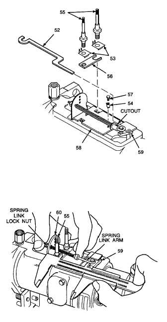
ASSEMBLE - Continued.
15.
INSTALL SHUTOFF BAR, KEEP PLATE, AND
SHOULDERED STUDS.
a.
Install shutoff bar (52) into cutout on
governor arm assembly (58).
b.
Install keep plate (56).
c.
Install lockwashers (53) over keep plate
(56), with tabs nearest to the metering valve
(59).
d.
Install shouldered studs (55) hand tight.
e.
Install lockwasher (54), with tail resting
below edge of governor arm assembly (58)
closest to metering valve (59).
f.
Install screw (57). Tighten to 21 lb-in (2
N•m).
g.
Tighten shouldered studs (55) to 60 lb-in (7
N•m).
h.
Use a flat-blade screwdriver to bend tabs
on lockwashers (54 and 53) up to secure
shouldered studs (55) and screw (57).
16.
ADJUST SPRING LINK LENGTH.
a.
Place a slide caliper between metering
valve
(59)
and
larger
diameter
of
shouldered stud (55), gently extending
metering valve as far as it can go, using the
inside measuring part of micrometer.
b.
When metering valve (59) is extended,
manually retract spring link (60) spring and
check that metering valve is fully open
(metering valve arm should almost touch
edge of fuel injection pump housing).
c.
To adjust length of spring link (60), loosen
spring link lock nut and adjust spring link
arm length.
d.
Tighten spring link (60) lock nut when
spring link arm length is correct.
GO TO NEXT PAGE
2-281


