TM 5-3895-373-34
2.16
ENGINE REPLACEMENT - Continued.
A.
REMOVE Continued.
NOTE
Right side mounting and support
brackets attached to pump drive
gearbox and flywheel housing can be
accessed
through
engine
access
cover in hopper.
d.
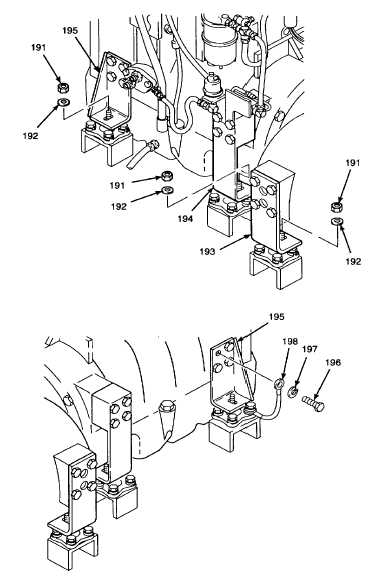
Remove self-locking hex nuts (191), and flat
washers (192) from pump drive gearbox support
brackets (193) and flywheel housing mounting
brackets (194) on both left and right sides of the
engine and pump assembly. Discard self-
locking hex nuts.
NOTE
Front engine mounting brackets can
be reached through access door
openings on left side of the paving
machine.
f.
Remove hex head cap
screw
(196)
and
lockwasher (197) securing engine ground wire
(198) to front engine mounting bracket (195).
Install hex head cap screw and lockwasher back
onto front engine mount.
Do not allow engine and pump
assembly to swing free from hoist
during
removal
from
the
paving
machine.
Engine
and
pump
assembly may strike personnel and
cause serious injury or damage to
machine if allowed to swing free.
Two additional personnel are needed
to help guide the engine and pump
assembly out of the machine during
removal.
g.
Position two persons on top of paving machine
over the valve panel to steady the engine and
pump assembly during removal. One person
should be stationed at pump end, the other
person should be stationed at he radiator fan end
on the opposite side.
GO TO NEXT PAGE
2-104


