TM 5-3895-373-34
C.
INSTALL Continued.
3.
INSTALL ROCKER SHAFT ASSEMBLY AND
PUSH
RODS
INTO
CYLINDER
HEAD
ASSEMBLY.
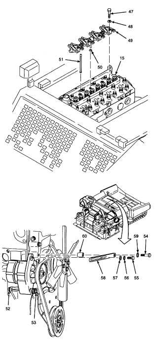
a.
Install
push
rods
(51)
into
cylinder
head
assembly (15). Make sure that the push rods
are installed in the same locations from which
they were removed.
b.
Place preformed packing (50) in the oil feed
connection recess of cylinder head assembly
(15).
c.
Install rocker shaft assembly (49) straight down
onto cylinder head assembly (15).
d.
Lightly oil screws (47) with engine oil.
e.
Install washers (48) and screws (47).
f.
Tighten screws to 30 lb-ft (41 N•m).
4.
ADJUST FAN BELT TENSION AND TIGHTEN
ALTERNATOR HARDWARE.
NOTE
Install, but do not tighten, any of the
alternator mounting hardware until
the fan belt tension adjustment has
been completed per TM 5-3895-373-
20.
a. Attach belt adjusting arm (58) and sleeve spacer
(60) with lockwasher (59) and hex head cap
screw (54). Do not tighten cap screw at this
time.
b. Ensure that fan belt is seated properly onto all
pulleys.
c. Install adjustment screw (55) and flat washers
(56 and 57) into alternator through belt adjusting
arm (58). Do not tighten the screw at this time.
d. Adjust fan belt tension and tighten alternator
mounting hardware per TM 5-3895-373-20.
NOTE
Before installing the valve cover,
perform valve adjustment procedure
per TM 5-3895-373-20.
GO TO NEXT PAGE
2-75


