TM 5-3895-373-20
2.24.3. SCREED REMOVAL AND INSTALLATION - Continued.
B.
INSTALL - Continued.
NOTE
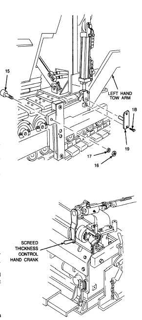
Installation procedure for left hand
and right hand tow point hardware is
the same. Left hand tow point
hardware is shown in this procedure.
2.
INSTALL TOW POINT HARDWARE.
Thread locking compound solvent
can cause eye damage. Wear safety
goggles/glasses when using. Avoid
contact with eyes. If solvent contacts
eyes,
flush
with
water
and
get
immediate medical attention.
a.
Clean threads of hex head cap screws (18) with
thread locking compound solvent. Wipe threads
dry with lint-free cloth.
b.
With throttle control switch in IDLE position, jog
left hand tow point movement switch up or down
per TM 5-3895-373-10 to line up hole in tow
point cylinder clevis with hole in tow arm. If
further adjustment is required, adjust tow arm up
or down with screed thickness control hand
crank. Install tow point locking pin (19).
Thread locking compound can cause
eye
damage.
Wear
safety
goggles/glasses when using. Avoid
contact with eyes. If compound
contacts eyes, flush eyes with water
and get immediate medical attention.
c.
Apply thread locking compound to hex head cap
screw (18). Install and tighten cap screw to 37
lb-ft (50 N•m).
d.
Install roller (15), washer (17), and hex nut (16).
Hold head of roller with flat head screwdriver bit
and socket wrench. Tighten hex nut.
e.
Repeat steps b through d at right hand tow arm.
f.
Shut off engine and remove key from ignition
switch per TM 5-3895-373-10.
GO TO NEXT PAGE
2-462