TM 5-3895-373-20
2.24.3. SCREED REMOVAL AND INSTALLATION - Continued. ,.
A.
REMOVE - Continued.
NOTE
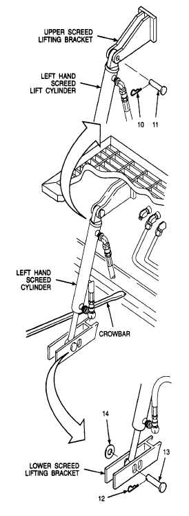
Disconnection
procedure
for
left
hand and right hand screed lift
cylinders is the same. Left hand
screed lift cylinder is shown in this
procedure.
3.
DISCONNECT SCREED LIFT CYLINDERS.
a.
Check that screed vibrator, extension screed
control, and burner fuel pump switches are
turned to the OFF position at operator switch
panel and screed control panels per TM 5-3895-
373-10.
b.
Pull lock pins (10) from left hand and right hand
screed lift cylinders.
c.
Start up paving machine and place screed lift
switch in down, FLOAT position per TM 5-3895-
373-10.
d.
While another person uses crowbar to pry up on
cylinder tube of each screed lift cylinder, remove
clevis pins (11).
e.
Place screed lift switch in up, RAISE position
and partially retract cylinders. Leave cylinder
piston rods extended 6 to 8 in. (150 to 200 mm).
f.
Shut off engine and remove key from ignition
switch per TM 5-3895-373-10.
g.
Note which pin slot (front or back) is being used
in lower screed lifting bracket. While lifting up on
the screed lift cylinder have another person pull
lock pins (12), clevis pins (13), and flat washers
(14).
GO TO NEXT PAGE
2-458