TM 5-3895-373-20
15.17. REPLACE/REPAIR FEED LIMIT SWITCH PADDLE ASSEMBLY - Continued.
C.
INSTALL Continued.
2.
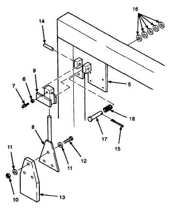
INSTALL FEED LIMIT SWITCH PADDLE
CONTROL ARM.
a.
Position actuator mount (9) onto endgate
support arm (5) and secure with spring pins (14).
b.
Place control arm rubber extension (13) on feed
limit switch paddle (8) and secure with hex head
cap screws (12), flat washers (11) and self-
locking nuts (10). Tighten to 108 lb-in (12 N•m).
c.
Place hex nut (6) onto thumbscrew (7) and
install into actuator mount (9).
d.
Install spring (18) onto straight headed pin (17)
and install into endgate support arm (5).
NOTE
Flat washers are installed on straight
headed pin (17) in front or back of
endgate support arm (5). Washers are
installed on pin to adjust pin length to
prevent paddle assembly from actuating
feed limit switch with no paving material
present.
e.
Observe contact on arm of actuator mount (9).
Add flat washers (16), as required, between
spring (18) and endgate support arm (5), to
allow arm of actuator mount to touch the head
of straight headed pin (17) and actuate feed
limit switch with no compression of spring.
f.
Install flat washers (16) as required on back of
straight headed pin (17) behind endgate support
arm (5) to fill space between support arm and
cotter pin hole. Install cotter pin (15).
g.
Insert feed limit switch paddle (8) into actuator
mount (9). Tighten thumbscrew (7) and snug
hex nut (6).
NOTE
FOLLOW-ON-TASK: Install endgate hand lever assembly per paragraph 15.16.
END OF TASK
15-124


