TM 5-3895-373-20
NOTE
This procedure applies to both the
left and right feed limit switch paddle
assemblies. For this procedure the
left paddle assembly is shown. The
procedure
for
the
right
paddle
assembly is identical.
A.
REMOVE.
1.
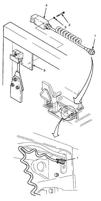
REMOVE FEED LIMIT SWITCH ASSEMBLY.
a.
Disconnect limit switch electrical connector (1)
from the connector on the paving machine
bulkhead.
b.
Remove socket head cap screws (2) and
lockwashers (3). Discard lockwashers.
c.
Remove feed limit switch assembly (4) from
endgate support arm (5).
GO TO NEXT PAGE
15-117