
TM 5-3895-356-14&P
24. If previously removed, Install two plugs (33) with new
NOTE:
O-rings (34).
Units' of recent manufacture utilize male shuttle valves
with female shuttle plugs Older units used female shuttle
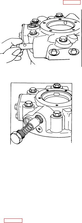
25. Install shuttle (32) in cover (4) See Fig 224.
valves and male shuttle plugs Where it becomes
necessary to replace either the shuttle or the plugs, be
certain the faulty piece Is replaced with one of a like kind.
Dynapower motors have been manufactured with three
high pressure relief valve configurations as illustrated
below To complete assembly, identify relief valve
configuration and proceed as Instructed.
Figure 224.
Installing shuttle valve
Figure 225.
Installing low pressure relief valve
Check for free movement from side to side If any
tightness is felt, remove any nicks or burrs with 500 grit
emery It Is essential to the proper operation of the
relief valve system that the shuttle valve operate freely
Install shuttle plugs (35) with new O-rings (17).
26. Inspect low pressure relief valve plunger (61) for
scratches, nicks or burrs. Burnishing of the plunger at
the point of contact with the seat is normal If wear can
be felt, replace the plunger (61) Install the plunger (61),
spring (62), a new O-ring (17), and relief valve plug
(73) See Fig 225.
127