
TM 5-3895-356-14&P
TYPE III
Type III
See Fig 235.
C-1 Install O-rings (52) and back up rings (51) being
certain that they are installed In the manner
C-2 Insert relief valve body in motor cover and secure
with hex bolts (48 & 50) and lock washers (47) Torque to
132 in lbs See Fig 227.
Figure 226.
Phase III motor cover
See Paragraph C below.
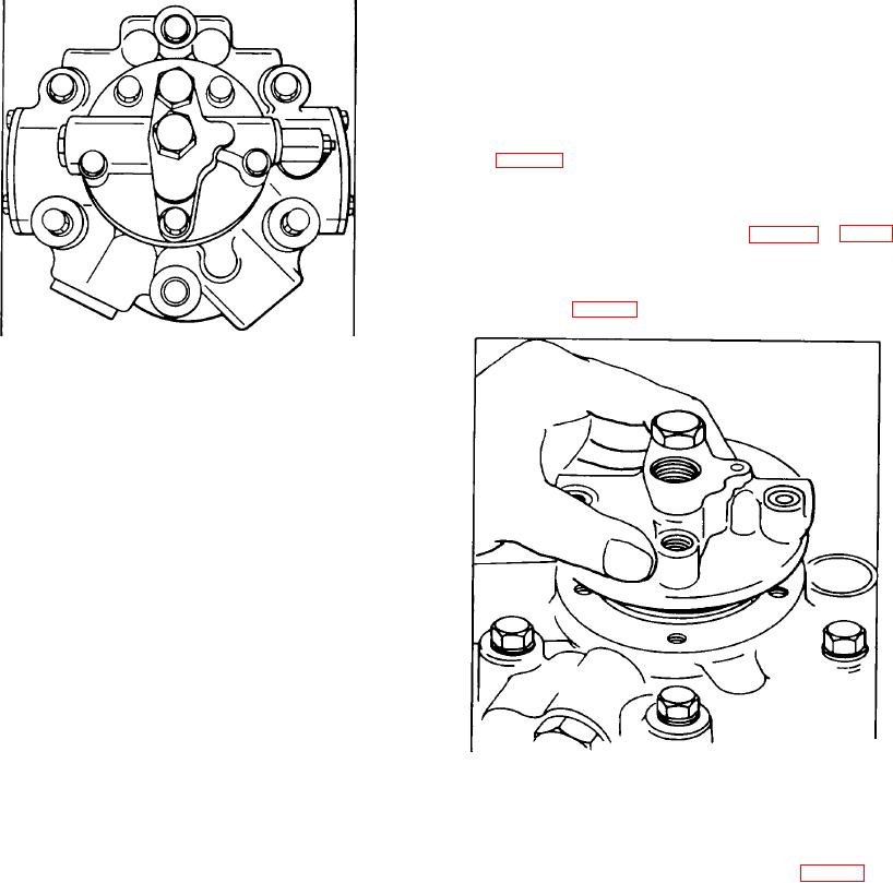
Figure 227.
Installing high pressure relief valve body
C-3 Inspect high pressure relief valve pilot (13) Under
normal usage, a seating pattern will burnish on face of
pilot (13) If seating pattern can be felt or If the pilot is
damaged In any way, It must be replaced See Fig 228.
128