
TM 5-3895-356-14&P
13. Carefully, remove four hex nuts (12) and lock
washers. (13). Lift off cylinder cover (43) including O-
ring (46). Pull transfer tube (17) and two O-rings (14)
from the seat in either the control housing (57) or the
cylinder cover (43). See Fig. 170.
Figure 170.
Cylinder cover with transfer tube
14. Remove servo tube (16) with servo plunger
assembly, from control housing (57). Slide the servo
plunger assembly (45) and (67) from servo tube (16) and
remove two O-rings (46), one from the piston (45) and
one from the control housing (57). See Fig. 171.
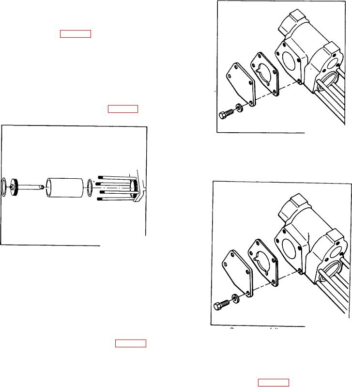
Figure 172.
Control housing cover
Omit Step 18 if servicing a Low Pressure Servo or Short
Differential Pressure Compensated Override Control.
Figure 171.
Cylinder with servo plunger
15. Remove selflocking nut (44), washer (66), and piston
(45) from rod assembly (67).
16. Inspect servo studs (15). Remove only if the threads
have been damaged or if the studs are twisted or broken.
Figure 173.
17. Remove four hex bolts (24), lock washers (25),
Removing cam follower
housing cover (26), and gasket (27). See Fig. 172.
19. If necessary, the orifice (53) may be removed by first
removing stud (15) to gain access to pipe plug (51).
With an Allen wrench, remove pipe plug (51), spring (52),
and orifice (53). See Fig. 174.
This completes disassembly of the horsepower control.
CONTROL ASSEMBLY
Keep the work area and all parts absolutely clean.
Remove all old oil and grease from parts prior to
reassembly.
108