
TM 5-3895-356-14&P
forward and backward from detented position to confirm
free travel to servo plunger.
22. Place a new gasket (65) on pump (or -motor)
housing using a thin coat of clean transmission oil to hold
it in place.
23. Position control housing (57) so that rod link (72)
slips into slot in pump cam arm. Place a clean shop rag
around the cam arm and insert clevis pin (73) with one
new E-ring (71) attached in counterbored side of cam
arm and through rod link (72). Install the 2nd new E-ring
on clevis pin (73).
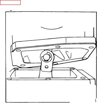
See Fig. 181.
Figure 181.
Cam actuator arm & cam follower.
24. Install new O-ring (70) in seat on pump (or motor)
housing using a thin coat of grease to hold it in place.
25. Install control assembly to pump (or motor) using
four short and two long hex bolts (items 28 & 38) and six
lock washers, making sure the slot in the valve
sleeve assembly (22) is positioned over the pin on
the cam lever assembly and that the O-ring (70) is
properly seated. Torque 6 hex bolts to 132 in. lbs.
26. Install two cap screws (76), two spacer (77), two lock
washers (25) and detent plate (75). (If one of two cap
screws (76) was wrapped with tape in Step 3, be certain
it is positioned at the end of the cam follower pivot
through hole and opposite cap screw (24) prepared in a
similar manner) tighten cap screws (76) by hand; do not
torque tight.
112