
TM 5-3895-356-14&P
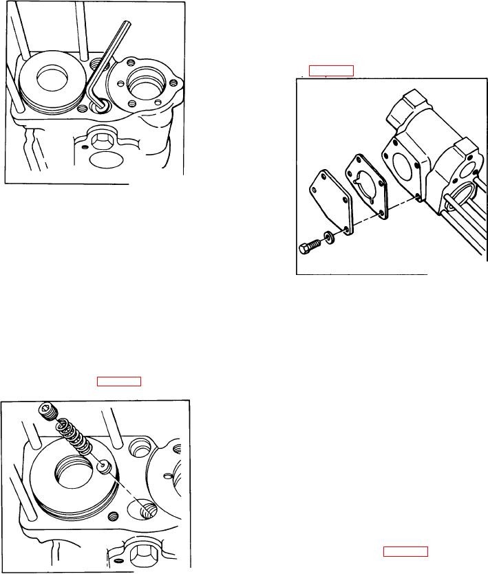
5. Install housing cover (26) with four cap screws (24),
lock washers (25), and a new gasket (27). If one cap
screw (24) was prepared with tape in Step 4, be certain it
is positioned at the end of the cam follower pivot through
hole). See Fig. 176. Torque cap screws to 132 in. lbs.
Figure 174.
Removing orifice
During reassembly, check all moving parts for smooth
operation. It is essential that there be no binding or
interference between any internal moving parts.
This procedure is also applicable to the low pressure
servo control and the short differential, pressure
Figure 176.
compensated override control. When servicing either of
Control housing cover
these control types, omit the appropriate steps where
indicated.
6. If removed during disassembly, inspect four studs
(15) for damaged threads, bends, twists or cracks and
1. Inspect servo rod bushing (68).
replace if necessary. Use Loctite sealant, Grade 3, on
coarse threaded end of studs and install in housing (57).
2. If removed during disassembly, install orifice (53)
Torque studs down tight.
and spring (52) with plug (51) using Loctite pipe sealant.
Torque plug down tight. See Fig. 175
7. Inspect piston (45) for nicks or scratches around the
perimeter. If observed, replace piston (45). Inspect link
end of rod assembly (67) for cracks. Replace rod
assembly (67) if cracks are found. Install piston (45) on
rod assembly (67) with washer (66) and selflocking nut
(44). Torque selflocking nut (44) to 420 in. lbs.
8. Install three new O-rings (46) on housing (57), piston
(45), and cylinder cover (43). Install servo plunger
assembly in control housing (57).
9. Lubricate the entire inner surface of cylinder tube
(16) with clean transmission oil. Install cylinder tube (16)
over servo piston assembly (45) and seat tube (16)
against housing (57). See Fig. 177.
10. Install two new O-rings (14) on each end of transfer
Figure 175.
tube (17). Lubricate the ends of the transfer tube (17)
Plug, spring & orifice
and insert in cylinder cover (43). Install cylinder cover
NOTE:
(43) with new O-ring (46) and transfer tube over studs
Omit Step 3 and 4 if servicing a Low
(15) and seat into end of servo
Pressure Servo Control.
Omit Step 3 if servicing a Short
Differential Pressure Compensated
Override Control.
109