TM 5-3895-356-14&P
pump gears (47) over keyway on shaft (1). Check for
proper key engagement by attempting to rotate inner
gear on shaft. If gear turns on shaft, remove gear,
reposition key and repeat installation of gears.
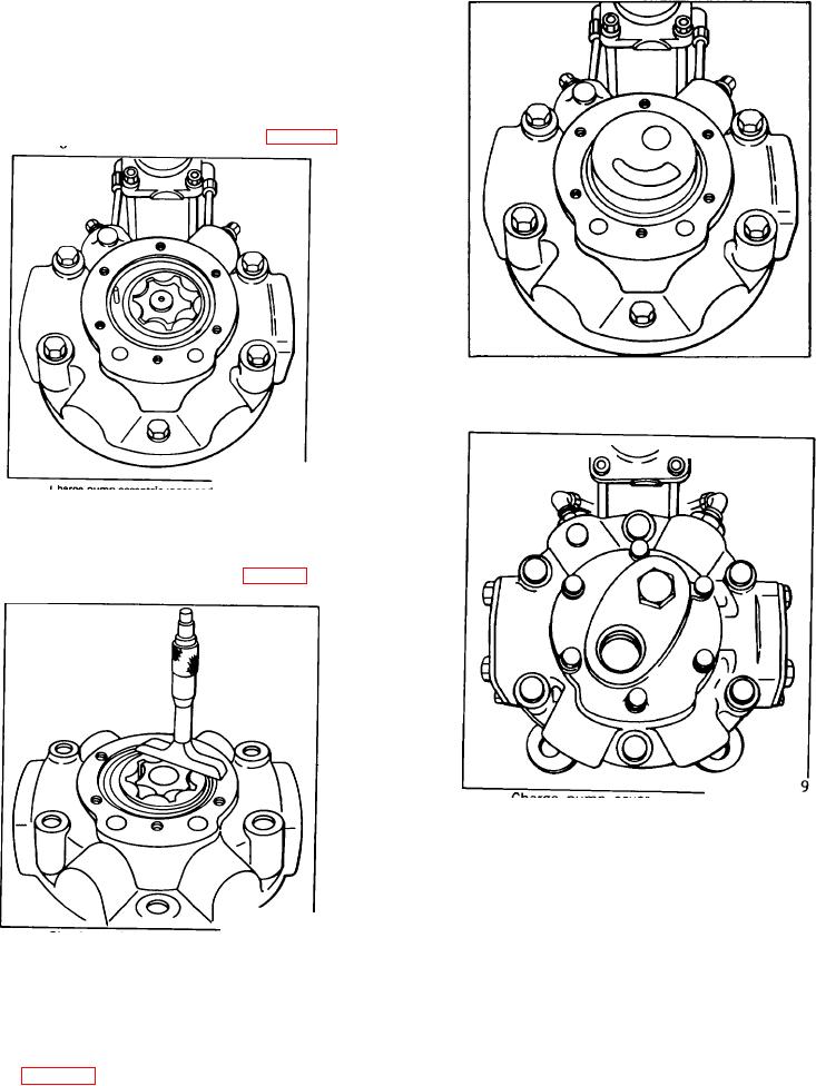
33. Install the charge pump spacer (48) over the charge
pump gears (47) positioning the short end of the roll pin
in the lower charge pump valve plate. See Fig. 156.
Figure 158
Charge pump upper valve plate
Figure 156.
Charge pump eccentric inner and outer gerotor
Use a depth gauge to confirm .001-.0035 clearance
between the top of the charge pump spacer (48) and the
top of the charge pump gears (47). See Fig.157.
Figure 159.
Charge pump cover
38. Rotate pump shaft (1) to check for binding in the
charge pump. If shaft will not turn, remove charge pump
cover (10) and upper valve plate (45). Re-check charge
pump tolerances as described in
Figure 157.
Checking charge pump clearance
34. Install new 0-ring (44) to outside of charge pump
spacer (48). The direction of pump rotation is indicated
by an arrow cast on the charge pump cover.
Install upper valve plate, over roll pin in spacer assembly
(48). See Fig. 158..
103

