
TM 5-3895-356-14&P
OVERHAUL - LONG DIFFERENTIAL PRESSURE
COMPENSATED OVERRIDE CONTROL
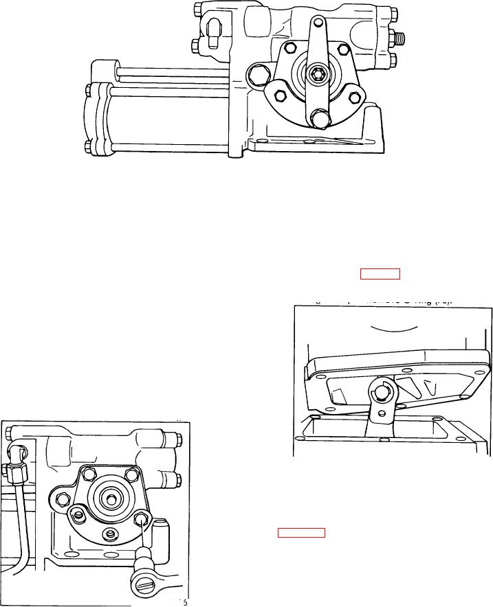
Figure 165.
The following procedure details the removal and
2.
overhaul of the standard horsepower control with
Remove six bolts (4 short, 2 long)
adjustable neutral detent.
items (28) & (38), and six lock washers (63).
This procedure is also applicable to the low pressure
3. Lift control assembly from pump housing, breaking
servo control and the short differential pressure
the seal with gasket (65). Care should be taken to avoid
compensated override control. When servicing either of
bending the feedback lever (22) by swinging it to one
these control types, omit the appropriate steps where
side, as illustrated in Fig.167 before proceeding to Step
indicated.
4. Remove O-ring (70).
ALL PART NUMBERS IN PARENTHESIS FOLLOWING
THE PART NAMES REFER TO TO THE INDIVIDUAL
PARTS AS IDENTIFIED IN FIGURE 238 EXCEPT AS
NOTE D.
CONTROL DISASSEMBLY
1.
Remove lock
nut (41), washer (40) and lever assembly (82)
Remove
two cap screws (76),
two lock
washers (25)
Fig. 166.
Figure 167.
Cam actuator arm and valve sleeve
4. With a small screwdriver, remove E-ring (71) from
the side of the cam arm opposite the counterbore. A
clean shop rag should be positioned around the cam arm
to prevent the loss of the E-ring into the pump housing.
See Fig. 168.
5. Remove clevis pin (73) with 2nd E-ring and slip the
control link (72) from the cam lever. Remove gasket
(65) from control housing.
6. Remove two cap screws (74) and two lock washers
(25). Slip seal plate assembly (42) off over control valve
Figure 166.
(23).
Fig. 166. Removing adjustable neutral detent
106