
TM 5-3895-356-14&P
cover (9). Apply vaseline to O-rings (62) and install
surface to remove any high spots. Inspect charge pump
plugs (61) in cover.
spacer assembly (48). If any galling or excessive wear is
apparent, discard the spacer assembly (48).
See
Fig.153.Remove any burrs with a hard Arkansas stone or
equal to remove 'any nicks from the flat faces.
29. Position O-ring (41) over cover bearing (50).
Lubricate the entire charge pump cavity with clean
transmission oil.
30. Install lower valve plate (42) over cover bearing (50)
and O-ring (41). See Fig. 154.
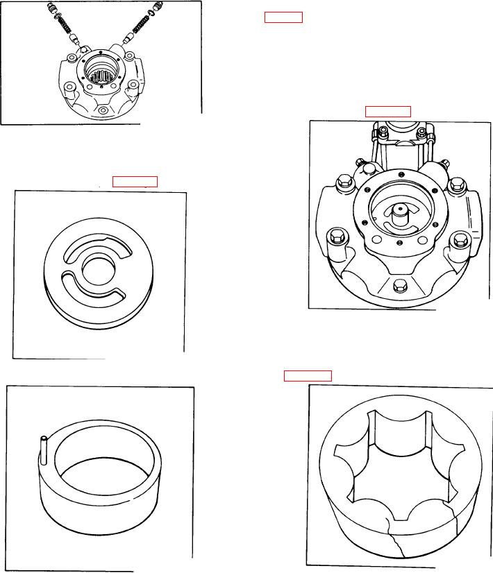
Figure 151.
Pump cover with assembled parts
28. Visually inspect upper (45) and lower (42) valve
plates. If circular wear patterns can be felt, discard both
the upper and lower plate. See Fig. 152.
Figure 154.
Charge pump lower valve plate
31. Inspect charge pump inner and outer rotor (47) for
damage or excess wear. If inner or outer rotor are
scratched or galled, the gears must be replaced as a set.
Figure 152.
See Fig. 155.
Inspecting charge pump upper valve plate
Figure 155.
Inspecting outer rotor
Figure 153.
Rotate one gear within the other to check for free action.
Inspecting charge pump eccentric
If action seems stiff in a particular area, use a hard
If wear patterns cannot be felt. inspect valve plates
Arkansas stone and lightly touch up the gear edges. Re-
for nicks and burrs. Rub flat faces and the outside edge
check for free rotation.
with 500 grit emery paper on a lap
32. Position key (46) in shaft keyway. Install charge
102